| GENERAL INFORMATION The SENTINEL VACUUM CONTROLLER is a diaphragm operated pneumatic valve. With proper installation, it is capable of maintaining a stable vacuum with +- (plus/minus) .2" Hg. over an adjustable range of 10'' - 15" Hg. at the regulator. The SENTINEL VACUUM CONTROLLER has been designed to correct several serious faults inherent in other types of regulators. 1. The SENTINEL is not load sensitive. It may be adjusted to a desired vacuum level with or without the milking units on the line. This is particularly valuable to the dairyman who milks with a varying number of units. As each unit is removed or added to the system, the Sentinel will automatically compensate for the changing load. In areas where testing devices are used, no readjustment is necessary to correct for the additional load of the units on the pipeline. However, it cannot offset the pressure drop which occurs in the claw due to the weigh device being in series with the milk hose on each unit. 2. The SENTINEL has a fully open to a fully closed span of .2" Hg. This means that when the vacuum rises or falls more than .2'' Hg. the regulator will open to maximum or close. It is not unusual to see most weight type regulators still admitting air into the system although the vacuum level has fallen 2 or more inches. 3. The SENTINEL will return to its set-point within .l" after a drop in vacuum level caused by a leak into the system. 4. The SENTINEL is easy to adjust. It may be set within .l" Hg of the desired level with a special wrench supplied with each regulator. This key is designed to prevent unauthorized personnel from changing the vacuum level, without the owner's consent. 5. SENTINEL VACUUM CONTROLLERS never completely shut off, therefore, a small amount of air is always passing through the unit, even when the poppet is in the closed position. The reason for this air pass-by is because of the .003 clearance between the poppet and the body of the unit. This clearance is necessary to minimize friction, thereby allowing instantaneous reaction to changes in vacuum levels. The amount of air that passes by the poppet is called air pass-by and amounts to approximately 10 CFM in the Model 100, 15 CFM in the Model 350 and 25 CFM in the Model 500. 6. Filter gauges (standard with models 500, 350 and 100, part #348-12) indicate the condition of vacuum controller filters. When the button on the filter gauge pulls in flush with the face, the filter should be changed for dependable operation. OPERATING PRINCIPLE
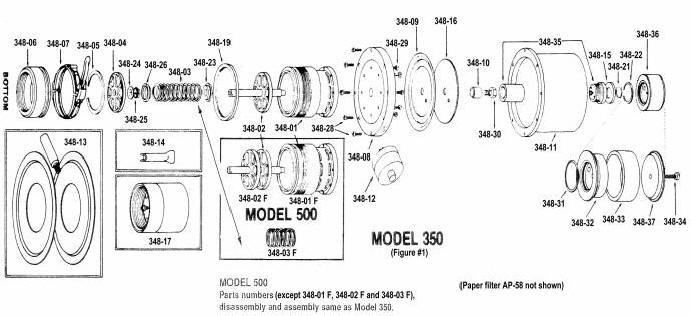
(Refer to Figure #1) As vacuum is applied on first system start up, a vacuum is drawn on the bottom side of the diaphragm (348-9), through the main sensing port located in the bottom of the poppet shaft. The regulator is biased at approximately 3.0" Hg. via the spring (348-3). The vacuum is drawn into the dome (348-11) through the hole in the diaphragm. Once the desired set point is reached, the bellows assembly (348-35) admits air into the dome through dome filter assembly (348-36) and felt filter (348-15), passing through the regulating seat in bellows assembly into the dome (348-11) thus maintaining a constant vacuum in the dome. This vacuum is 3.0'' Hg. below the regulating point of the controller. EXAMPLE: Controller set at I0'' Hg, thus giving 13.0'' Hg. regulating point. At this point the diaphragm is in a balanced condition. Any rise in vacuum will move the diaphragm (348-09) in a downward direction thus opening the valve wider. Any drop will move the diaphragm toward the dome, causing the valve to close. Since the resistance of the moving assembly is very low, a fully open to fully closed range of ± .2 Hg may be obtained. Figure #1 Model 350/500 Parts List | 348-01 | Body M-350 | | 348-01 F | Body M-500 | | 348-02 | Poppet Assembly M-350 | | 348-02 F | Poppet Assembly M-500 | | 348-03 | Spring M-350 | | 348-03 F | Spring M-500 | | 348-04 | Poppet guide | | 348-05 | Large bottom snap ring | | 348-06 | Inlet adapter | | 348-07 | Quick disconnect clamp | | 348-08 | Flange | | 348-09 | Diaphragm assembly | | 348-10 | Diaphragm retainer | | 348-11 | Dome | | 348-12 | Air Filter Gauge | | 348-13 | Large Filter Adapter kit | | 348-14 | Adjusting wrench | | 348-15 | Top felt filter | | 348-16 | back-up plate | | 348-17 | Relief valve | | 348-19 | Filter retaining ring | | 348-21 | small top snap ring | | 348-22 | large top snap ring | | 348-23 | Spring guide | | 348-24 | Damping collar complete | | 348-25 | Damping collar spring only | | 348-26 | Damping collar retainer | | 348-28 | Dome screws 8-32 x 5/8 | | 348-29 | Flange screws 10-32 x 5/8 | | 348-30 | Diaphragm bolt | | 348-31 | Top dome filter o-ring | | 348-32 | Filter cartridge holder (bottom) | | 348-33 | Filter replacement cartridge | | 348-34 | Top cartridge filter holding screw | | 348-35 | Aneroid assembly complete | | 348-36 | Top dome filter complete | | 348-37 | Filter cartridge holder (top) | | AP-58 | Large paper filter |
MOUNTING INSTRUCTIONS 1. The SENTINEL VACUUM CONTROLLER should be mounted at approximately eye level for maximum ease of periodic servicing (changing filters when required). Avoid, whenever possible, mounting close to hot water heaters and vacuum pumps, especially in small engine rooms or confined areas with poor ventilation. 2. Install as close to sanitary trap as possible if maximum control is desired. A tee with an automatic drain on the bottom should be provided to insure drainage after wash-up. 3. Avoid mounting on reserve tanks or headers whenever possible. In some cases this can result in a pipe-organ effect and cause an oscillation or pulsing problem. If this is encountered, a double elbow or offset may be necessary to break up direct airflow beneath the regulator. In some cases placement in a different location may be required. For best results mount the Model 100 with a 2" elbow below it and mount the Model 350 and Model 500 with a 3" elbow below it. For example, when mounting a Model 350 on a 4" vertical line, first place a 4" to 3" conversion T in the line, then come out with 6 to 12 inches of 3" pipe, then place a 3" - 90 degree elbow, add approximately 3 to 6 inches of 3 inch line upwards, place the inlet adapter, then attach the bottom of the Model 350 with the quick disconnect clamp to the inlet adapter. If you are mounting a Model 350 or Model 500 on a horizontal line between two receiver groups, place a T similar as above, on its side, in the middle of the line separating the two receiver groups. Then add a 6" piece of horizontal pipe, then place a 3" elbow pointing upwards, then add 3 inches of 3" pipe and then add the inlet adapter. 4. It is not necessary to use a pipe wrench to tighten the regulator to the line. A small amount of pipe dope or Teflon tape should be used before installation to provide a seal and prevent galling. 5. Do not reduce the pipe-size the regulator is mounted on to a size less than the diameter of the regulator base, unless the entire system's pipe size is smaller in diameter than the diameter of the regulator base. EXAMPLE: On the model 100, do not reduce below 1 1/2" NPT. 6. At no time should any type lubricant be applied to the regulator (especially WD40). Such lubrication will only cause a collection of foreign particles, restricting movement and eventually destroying the silicone rubber diaphragm. 7. At the time of installation, the customer should be instructed in the adjustment and filter replacement procedure. If the customer is not under a regular service program with his dealer, he should be shown the procedure for cleaning and routine care. 8. Adjustment of desired vacuum level is simply made with the special steel wrench provided with each regulator. Follow these steps: (A) Remove the snap-on top dome filter. (B) Looking down from the top, insert the adjusting wrench in the center of the piece on the top of the dome. (C) Clockwise rotation of the adjusting screw will raise the level, counter clockwise will lower the setting. 9. Upon initial starting of the vacuum pump, the regulator will open fully and then gradually begin to close until its set-point is reached. It is recommended that all drains and valves be closed before system start-up. If too many leaks into the system are permitted and the pump cannot pull at least 8" Hg., the regulator may remain open. The filter gauge provided on Models 500, 350 and 100 has a black button an its face. This button will pull in flush when it is time to change filters. The regulator will automatically correct for filter restrictions of up to 30" H20. But beyond this point sufficient air cannot be taken in to keep vacuum levels down to the desired point. 10. The filter retaining ring must be checked periodically to insure a firm seal. New filters tend to take a cold set and become loose. If this occurs, dirt and foreign particles will by-pass it and become lodged on the moving parts. This may cause sluggish or erratic regulation. It is recommended that each time the filter is changed, the bottom half of the unit below the flange (348-08 Model 350/500, 353-02 Model 100) be washed out with warm water solution of mild liquid household detergent. (DO NOT USE PIPELINE SOAP OR OTHER POWDERS HAVING CAUSTIC COMPOUNDS IN THEM.) 11. If frequent filter change is encountered a large filter adapter kit is available (348-13 Models 350/500 and 353-13 Model 100). Also, the Peacekeepers for each model provide larger filters. 12. Relief Valves (348-17 and RV-463) are offered as optional equipment. They should be mounted between the pump and the vacuum controller. Relief Valves are factory set but should be reset on any given system because sizes of systems will vary. Settings can be adjusted to a higher vacuum by turning the screw clockwise and lower by turning the screw counter-clockwise. The adjustment screw is located in the center of the threaded end of the Relief Valves. Further instructions regarding placement and setting are available in an instruction sheet accompanying the valves. DISASSEMBLY PROCEDURE
(Model 350 - refer to Figure #1) The Model 350 Sentinel may be disassembled in the field for inspection or repairs in the following manner: 1. Remove regulator from line by unscrewing the quick disconnect clamp (348-07). 2. Remove filter retaining ring (348-19). 3. Remove and set aside top dome filter (348-36). 4. Place regulator on table, using soft clean cloths as a cushion, with the dome down and with guide (348-04) facing up. Grasp body (348-01) with fingers and apply pressure to guide with thumbs in a downward direction. This will force guide away from snap ring (348-05). Remove snap ring while holding guide down with one hand, being careful not to let spring tension force guide out too quickly. Allow guide to come out. This is a precision fit and a slight rocking or shifting motion may be necessary should it become bound. Under no circumstances should anything be use to pry it out. 5. Remove damper ring assembly (348-26; 348-24; 348-25) noting position. 6. Remove spring (348-03). 7. Remove spring guide (348-23) noting position. 8. With a screwdriver of the proper blade width, remove the 8, 8/32 x 5/8 stainless steel screws holding the dome (348-11) to the flange (348-08). 9. Inspect the dome (348-11) for dirt or small foreign particles. If any are found, clean out with a clean lint-free cloth. 10. Set dome aside, open side down, to prevent dust or other contaminants from collecting in it while removed. 11. Remove diaphragm securing bolt (348-30) and set aside. (The poppet must be held by hand to prevent turning). 12. Remove diaphragm retainer (348-10). 13. Remove diaphragm by lifting outer edge, where fitted into flange, with fingernail or soft pointed object. Do not use a screwdriver or other sharp metallic object. Remove from shaft. 14. Inspect silicon-rubber diaphragm for holes or tears. If even the smallest puncture is noted, diaphragm must be replaced. 15. The poppet and shaft (348-02) may now be removed from the body (348-01). These are a unit and no attempt should be made to remove the poppet from the shaft. Often, there is sufficient dirt and build up to retard removal of the poppet from the body. If severe resistance is encountered, soak the body and poppet in warm water and a mild liquid detergent solution to remove build up. Do not use powdered pipeline cleaners or other soaps which may contain caustic compounds. Tapping lightly with a rubber hammer may be necessary. 16. Inspect poppet for nicks and abrasions. If any are found on the face, poppet must be replaced. Any attempt to file or emery the poppet should be avoided. 17. All of the various parts may now be washed in a mild soap solution and may be scrubbed with a non-abrasive brush. Do not use steel wool or scouring pads as this will mar the anodized plating. 18. If it is necessary to remove the aneroid assembly (348-35) from the dome (348-11), a special set of tools is required. This tool set includes an aneroid removal wrench and a bellows wrench. 19. Remove the aneroid by holding the top ring with the aneroid wrench and inserting the bellows wrench into the dome and unscrewing the aneroid cap from the aneroid bellows. 20. Remove all traces of silicone sealant compound from the threads and any that has adhered to the dome. 21. Inspect the rubber seat for damage or foreign particles in the small center hole of the aneroid bellows. 22. Inspect the stainless steel seat for dirt build up and remove by washing. Do not scrape with sharp objects. REASSEMBLY MODEL 350
(Refer to Figure #1) Care must be taken to keep all foreign particles and dirt out of the work area when assembling the controller. A clean, smooth table or bench should be used. 1. After carefully cleaning all parts, the controller may be reassembled, making sure there are no dust or lint particles in the dome (348-11). The aneroid assembly is replaced by applying a small amount of silicone sealing compound on the male threads. During insertion into the dome, some silicone will come off on the dome. Rotate after it makes contact with the dome to give an even seal. Then from the bottom, thread the bottom half of the aneroid ( aneroid bellows 348-35B) onto the projecting piece (aneroid cap 348-35C). Being careful not to cross-thread or bind it, tighten down with the aneroid wrenches only. Do not attempt to use any other type of tool, since damage is sure to result. 2. Wipe away any excess silicone sealer from the top of the dome and aneroid. 3. Inspect the inside of the dome for any loose or foreign particles and remove with a clean lint-free cloth. 4. Place the dome, large flanged end down, on a clean surface until ready for reassembly. 5. After making certain that the body (348-01) is clean and free from scores, insert the poppet into the barrel. This is a precision fit and must not be forced. If resistance is met, apply a slight side-to-side motion to the stem, working the poppet into the barrel. 6. Replace the spring guide (348-23). 7. Replace the spring (348-03). 8. Replace the damping collar assembly (348-25, 348-25 and 348-26). 9. Replace the guide (348-04). 10. Push the guide into the barrel far enough to allow placement of the snap-ring into the inner groove in the barrel. 11. Slide the diaphragm onto the stem protruding from the top side of the flange (348-08). 12. Insert the lip of the diaphragm into the groove. Work the edges of the diaphragm around evenly with your fingers to insure there are no wrinkles or uneven areas. 13. Place the stainless steel back-up plate (348-16) on top of the diaphragm. 14. Replace the diaphragm retainer (348-10) first placing a small amount of silicone sealer to the bottom edge of the retainer where it contacts the diaphragm plate. 15. Place a small amount of GE silicone sealer on the threads of the 5/16 diaphragm bolt (348-30) and screw into the top of the shaft. Place fingers in the poppet to retard rotation and snug down the bolt. Do not over tighten. 16. Place the dome open side up and carefully set the flange down over the screw holes. These are not keyed, but it is preferred that the port, that is for the air filter gauge, is located towards the front in line with the label on the dome. 17. Replace the eight 8/32 screws, dome screws (348-28), carefully, making sure that each is aligned and not cross-threaded. Tighten down evenly to a snug fit, making sure that the flange and dome are securely in place. Insert the filter pressure gauge (348-12) if it was removed. Put a small amount of grease on the threads and hand tighten only. 18. Install on vacuum system and adjust to the desired vacuum level. 19. Place the top dome filter complete (348-36) in place and re-check the vacuum level with it in place. It may cause a slight elevation in level in some instances. If this is encountered, simply adjust the controller to a slightly lower setting, then install the top dome filter to bring the vacuum level back up. If a rise of more than .5" Hg. occurs, replace the replacement filter (348-33). MODEL 500 Part numbers, disassembly and assembly of the Model 500 is the same as the Model 350, except for the poppet, body and spring. DISASSEMBLY PROCEDURE
(Model 100 - refer to Figure #2) 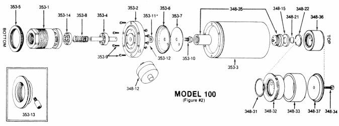
Model 100 Parts List | 353-01 | Body | | 353-02 | Flange | | 353-03 | Dome | | 353-04 | Poppet assembly | | 353-05 | Filter retaining ring | | 353-06 | Diaphragm | | 353-07 | Diaphragm backup plate | | 353-08 | Spring | | 353-09 | Dome screws (6) 10-32 x 5/8 | | 353-10 | Diaphragm bolt | | 353-11 | Bottom diaphragm washer (obsolete after serial no. 1200) | | 353-12 | Flange screws 10-32 x 5/8 | | 353-13 | Large filter adapter kit | | 353-14 | Poppet guide | | 348-12 | Air filter gauge | | 348-15 | Top felt filter | | 348-21 | Small top snap ring | | 348-22 | Large top snap ring | | 348-31 | Top dome filter o-ring | | 348-32 | Filter cartridge holder (bottom) | | 348-33 | Filter replacement cartridge | | 348-34 | Top cartridge filter holding screw | | 348-35 | Aneroid assembly complete | | 348-36 | Top dome filter complete | | 348-37 | Filter cartridge holder (top) | | AP-107 | Main paper filter (not shown) |
The Model 100 Sentinel is basically the same as the Model 350 in construction and operation. Disassembly and cleaning differ only in the following steps. Step #1 - The Model 100 must be unscrewed from the line, as it has no quick disconnect clamp. Step #2 - The poppet (353-04) can not be removed from the bottom of the barrel as with the Model 350. In order to remove it, the flange screws (353-12) must be removed allowing the body (353-01) to be separated from the flange (353-02), thus allowing the poppet to be removed from the top of the body. The aneroid assembly and top dome filter are interchangeable between the Model 100 and the Model 350. The diaphragm assembly and dome are the same design, and differ only in physical size. Insert a wooden pencil or soft object into one of the intake ports to hold the poppet open while replacing the diaphragm. Otherwise, the diaphragm will appear to be too small and not fit into the outer groove. Once the dome has been replaced, the pencil may be removed. DO NOT USE A SCREWDRIVER. Reassemble in reverse order. Please not the following: NOTE 1: The screw which holds the backup plate and diaphragm assembly must be sealed with silicone sealant. Very little sealant is required. Just enough to seal the shoulder of the screw to the backup plate. If excess sealant is allowed to extrude down into the poppet stem it can seal off the sensing hole in the side of the shaft and the regulator will not regulate accurately. NOTE 2: The diaphragm lip must be worked into the recess in the flange so there are no wrinkles or bulges prior to the dome installation. NOTE 3: To aid in the reassembly of the dome to the flange, a small scribe mark may be made, before disassembly, to align the screw holes. SPECIFIC INSTRUCTIONS TO THE CUSTOMER 1. Complete cleaning and performance instructions should be given to the user upon installation to insure the maximum performance and unnecessary call backs. 2. Emphasize the importance of routine cleaning of the lower body. 3. Daily check the air filter gauge. 4. Check weekly to insure the air filter retaining ring is tight. 5. Before each milking, check line vacuum as a routine check of normal operation. 6. When the main filter is removed or changed, the lower half of the body should be flushed out with a warm mild soapy solution of household detergent being careful not to submerge more than just the lower half. The usual build-up of carbon and fine dust particles are usually quite water soluble. 7. A weekly check is a must to insure maximum performance and proper operation. 8. Even though every effort has been made to insure trouble free performance and maximum life, a daily check of the vacuum level should be made as a routine procedure. 9. VISUAL QUICK CHECK To make certain your Sentinel Vacuum Controller is in balance with your system, take the following steps: A. Before turning your system on, remove the main filter from the vacuum controller. B. With the system operating, look through the windows in the body of the unit. You should see the poppet moving up and down. At no time, if operating properly, should the poppet window be more than half open. C. Be sure to replace the filter after this checking procedure. You should not operate your system for an extended period without the filter in place. TROUBLESHOOTING GUIDE | Symptom | Possible Cause | Cure | Sudden rise in vacuum | Ruptured diaphragm Foreign material in body Wet dome filter | Replace Wash with mild soap and water Replace with new filter | Slow rise in vacuum | Top dome filter plugged or dirty Dirty top felt filter Foreign particles in top reg. seat | Replace Replace Remove and clean | Vacuum too low | Dirty barrel and poppet Diaphragm pulled away from support plate but not ruptured Leak around dome flange Leak around aneroid | Clean Replace Tighten Reseal | Vacuum unstable | Unsuitable location for mounting Pulsator line tied in too close to controller Dirty poppet or body Controller capacity close to that of pump | Move to another location Move to another location Clean Use larger controller |
PAPER FILTER REFERENCES AP-107 filter for Model 100 replaces: | Gould AP107 | | Tecumseh 31925 | | Fram CA-76 | | WIX 42374 | | Baldwin PA1712 |
AP-58 filter for Model 350 (Standard) and Model 100 (with Adapter Kit) replaces: | Fram CA-102PL | | WIX 42112 | | Baldwin PA1648 | | Gould AP-58 |
Filters to use with Model 350/500 with large filter adapter kit (348-13) | WIX 42020 | | Fram CA160 | | Gould AP-4 |
Procedure for adapting the Gould AP-4 type filter to the Model 350/500 using the large filter adapter kit. 1. Remove the filter indicator gauge. 2. Screw in the brass adapter into gauge hole and reinstall filter gauge. 3. Remove the filter retaining ring and the old filter. 4. Place the spacer up under the flange plate. 5. Place one of the thin adapter plates up against the spacer. 6. Install the new filter. 7. Place another thin adapter plate up against the filter. 8. Screw on the filter retaining ring up snug against the bottom plate. 9. Check for filter tightness every day for the first few days, as the rubber on the filter has a tendency to take a cold set and may become loose with time. Procedure for adapting the Gould AP-56 type filter to the Model 100 using the filter adapter kit. 1. Remove the filter indicator gauge. 2. Screw in the brass adapter into gauge hole and reinstall filter gauge. 3. Remove the filter retaining ring and the old filter. 4. Install the new filter. 5. Screw the adapter on below the filter. 6. Check for filter tightness every day for the first few days, as the rubber on the filter has a tendency to take a cold set and may become loose with time.
GENERAL MAINTENANCE INSTRUCTIONS DO NOT OPERATE without top AND bottom filters in place. A. Replace bottom filter when filter gauge BUTTON pulls in flush. B. Replace top dome filter when vacuum gauge indicates over 1/2" Hg difference when top dome filter is momentarily removed during operation. When main filter is changed the lower half of the controller should be immersed in a warm mild soapy solution of household detergent being careful not to submerge more than just the lower half. Agitate several minutes and rinse. The usual build-up of carbon and fine dust particles are usually quite water soluble and can be removed in this manner. NEVER ALLOW LIQUIDS to enter top dome opening. NEVER USE pipeline wash solutions in the controller. General pipeline cleaners are corrosive and will dissolve aluminum. NEVER USE lubricants on the controller. Check line vacuum gauge and air flow gauge regularly to insure maximum performance.
| Under no circumstances do we feel this controller will eliminate the need for proper vacuum capacity and a good vacuum system in regard to line size and method of installation. |
General Specifications Model 100 Sensitive to 0.1" Hg change Adjustment range 8" 15" Hg Differential vacuum Reaction time to change: 50 milliseconds or less Finish: Hard anodized aluminum for maximum durability and corrosion resistance Adjustment screw (with special wrench to restrict unauthorized tampering) 1½" female NPT mounting Size: 5" diameter x 12¾" high Filters: a) Top dome filter, submicron; b) Main filter, standard cartridge type (LJE Part# AP-107) Maximum capacity: 150 CFM ASME at 15" Hg Direct Sensing Weight: 4 lbs. Nominal Air Pass-by: 10 CFM ASME Peacekeeper 462-100: Available noise suppressor with added filtration U.S. Patent No. 3,938,547
General Specifications Model 350 Sensitive to 0.1" Hg change Adjustment range 8"15" Hg Differential vacuum Reaction time to change: 50 milliseconds or less Finish: Hard anodized aluminum for maximum durability and corrosion resistance. Adjustment screw (with special wrench to restrict unauthorized tampering) 3" female NPT mounting Size: 7" diameter x 13¼" high Filters: a) Top dome filter, submicron; b) Main filter, standard cartridge type (LJE Part #AP-58) Mounting: Quick-disconnect stainless steel clamp Maximum capacity: 350 CFM ASME at 15" Hg Direct Sensing Weight: 10 lbs. Nominal Air Pass-by: 15 CFM ASME PEACEKEEPER 462-350: Available noise suppressor with added filtration U.S. Patent No. 3,938,547
General Specifications Model 500 Sensitive to 0.1" Hg change Adjustment range 8" 15" Hg Differential vacuum Reaction time to change: 50 milliseconds or less Finish: Hard anodized aluminum for maximum durability and corrosion resistance Adjustment screw (with special wrench to restrict unauthorized tampering) 3" female NPT mounting Size: 7" diameter x 13¼" high Filters: a) Top dome filter, submicron; b) Main filter, standard cartridge type (WDR Part #AP-58) Mounting: Quick-disconnect stainless steel clamp Maximum capacity: 500 CFM ASME at 15" Hg Direct Sensing Weight: 10 lbs. Nominal Air Pass-by: 25 CFM ASME PEACEKEEPER 462-350: Available noise suppressor with added filtration U.S. Patent No. 3,938,547
LIMITED WARRANTY: Seller warrants that the goods delivered shall be free from defects in material and workmanship for a period of one (1) year from the date of Sellers shipment. Sellers sole obligation and Buyers exclusive remedy for defects in the goods shall be limited, at Sellers option, to either repair or replacement of goods determined to be defective. Transportation and any other delivery costs to return defective goods to Seller for repair or replacement shall be the responsibility of Buyer. Any claim by Buyer must be made by Buyer to Seller in writing within five (5) days of the discovery of the claimed defect but in no event after the expiration of one (1) year from the date of Sellerss shipment, whichever is less. Buyers failure to so notify Seller of such defects within the above time periods shall bar Buyer from any remedy under this Warranty, or for recovery of damages or losses due to defects in the goods. Any return of goods shall be subject to the prior written approval of Seller. THIS WARRANTY IS THE SOLE WARRANTY COVERING THE GOODS AND SELLER MAKES NO OTHER WARRANTY OF ANY KIND, WHETHER EXPRESS, IMPLIED OR STATUTORY, AND ALL IMPLIED WARRANTIES OF MERCHANTABILITY AND FITNESS FOR A PARTICULAR PURPOSE ARE HEREBY DISCLAIMED BY SELLER AND EXCLUDED FROM THIS WARRANTY. IN NO EVENT SHALL SELLER BE LIABLE FOR CONSEQUENTIAL, COMPENSATORY, PUNITIVE OR INCIDENTAL DAMAGES HOWSOEVER ARISING FROM SELLERS PERFORMANCE OF THIS CONTRACT OR THE PERFORMANCE OF THE GOODS. This Warranty shall not apply to goods which have been repaired or altered by other than authorized representatives of Seller or to damage or defects caused by accident, vandalism, Acts of God, erosion, normal wear and tear, improper selection by Buyer or others, and other causes beyond Sellers control. This Warranty shall not apply to the misapplication, improper installation, or misuse of the goods caused by variations in environment, the inappropriate extrapolation of data provided, the failure of Buyer or others to adhere to pertinent specifications or industry practices, or otherwise. 2. LIMITATION OF SELLERS LIABILITY: Sellers liability on any claim of any kind, including claims based upon Sellers negligence, breach of contract, or strict liability in tort, for any loss or damage arising out of, connected with, or resulting from the use of the goods furnished hereunder or Sellers performance of this contract, shall in no case exceed the purchase price allocable to the goods or part thereof which give rise to the claim. IN NO EVENT SHALL SELLER BE LIABLE FOR SPECIAL, INCIDENTAL, OR CONSEQUENTIAL DAMAGES HOWSOEVER ARISING OUT OF SELLERS PERFORMANCE OF THIS CONTRACT AND NOTWITHSTANDING WHETHER SELLER MAY HAVE BEEN ADVISED OR IS ADVISED OF THE POSSIBILITY OF SPECIAL (OR LIQUIDATED) DAMAGES. 
GENERAL INFORMATION The SENTINEL MARK II is an updated version of the successful and popular Sentinel Mark I Vacuum Controller. The Mark II represents another significant advancement in vacuum controllers by L. J. Engineering, Inc. in its continuing leadership position since introducing the first diaphragm-operated vacuum controller to the dairy industry almost 40 years ago. The SENTINEL line of vacuum controllers has raised the standard of vacuum controller accuracy in milking, with the attendant operating benefits for dairies of all sizes. The SENTINEL MARK II is a low-cost, diaphragm-operated vacuum controller designed to provide high performance for milking systems of up to 150 CFM (cubic feet per minute, ASME) at 15" Hg (inches of mercury). (L. J. Engineering, Inc. offers other models of SENTINEL controllers for milking systems with greater air flow.) The MARK II is designed to provide proper vacuum stability - as well as a more balanced system - for safe and efficient milking at a relatively low cost. With proper installation the Mark II is capable of maintaining a stable vacuum within +-0.2" Hg over an adjustable range of 10" to 15" Hg at the controller under normal milking conditions. The SENTINEL MARK II VACUUM CONTROLLER provides the following performance features: The MARK II is not load sensitive to normal airflow (CFM) usage changes relating to normal milking conditions. It may be adjusted to a desired vacuum level with or without the milking units on the line. This is particularly valuable to the dairy which milks with a varying number of units. As each unit is removed or added to the system, the MARK II will automatically compensate for the changing load. In areas where testing devices are used, no readjustment is necessary to correct for the increased load of additional units on the pipeline. However, it cannot offset the pressure drop which occurs in the claw due to the weigh device being in series with the milk hose on each unit. The MARK II has a fully open to a fully closed span of 0.2" Hg. The MARK II will return to its set-point within 0.1" Hg. The MARK II is easy to adjust, requiring no tools. It may be set within 0.1" Hg of the desired level.
OPERATING PRINCIPLE The main valve consists of a rolling tube of rubber (406-14-rolling seal) which seals against a series of slots in the flow ring (406-04L). The poppet assembly (406-07) has a hole in it which permits ambient air into the cavity hehind the poppet, which is the side of the poppet assembly opposite the rod. The system vacuum sucks the rolling seal against the slots and seals them. A spring (406-13-closing spring) biases the valve in the closed position. As the system is started up, vacuum is sensed through the sensing ports in the flow ring (406-04L) and flange assembly (406-33L), and pulls the sensing diaphragm (406-17-main diaphragm) down, compressing the closing spring (406-13) and allowing ambient air to flow into the system via the flow ring (406-04L) slots. The vacuum under the main diaphragm (406-17) pulls air out of the dome (406-03) by means of two small holes in the main diaphragm (406-17). Since the dome (406-03) represents the reference vacuum for the controller, system vacuum will increase until the vacuum set-point in inches of mercury is reached. At that point, the vacuum in the adjuster housing (406-10) lifts the dome diaphragm (406-11) against the adjustment spring (406-19) and allows air into the dome. This flow balances the flow through the orifices in the main diaphragm (406-17) and so stabilizes the vacuum in the dome (406-03). INSTALLATION INSTRUCTIONS The SENTINEL MARK II VACUUM CONTROLLER should be installed at approximately eye level for maximum ease of periodic servicing (changing filters when required, etc.). Avoid installing close to hot water heaters and vacuum pumps, especially in small equipment rooms or confined areas with poor ventilation. The controller should be installed vertically or within 45 degrees of vertical. Install the MARK II as close to the sanitary trap as possible to achieve maximum control. An automatic drain should be provided to assure drainage after wash-up.
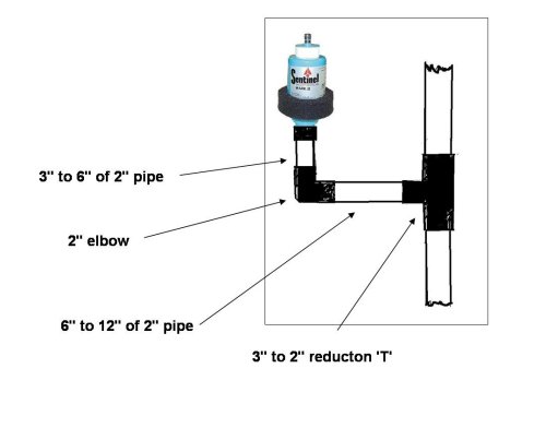
For example: On a 3" vacuum system use a 3" to 2" reduction 'T', connect to the 'T' approximately 6" to 12" of 2" straight pipe, then a 2" elbow, then another 3" to 6" of 2" straight pipe, then install the Mark II on a 2" coupling. FROM ELBOW TO MARK II DO NOT EXCEED 12 INCHES. Avoid installing on reserve tanks or headers whenever possible in some cases this can result in a pipe-organ effect and cause an oscillation or pulsing problem. If this is encountered, a double elbow or offset may be necessary to break up direct air flow beneath the controller. PLACEMENT IN A DIFFERENT LOCATION IS PREFERABLE. Do not reduce the pipe-size the controller is mounted on to a size less than the diameter of the controller base, (2"), unless the entire systems pipe size is smaller in diameter than the diameter of the controllers base. EXAMPLE: On a 3" vacuum system, do not reduce the pipe size below 2", when installing the Mark II. Do not use a pipe wrench to tighten the Mark II to the line. Hand-tight is sufficient. Teflon tape should be used to provide a seal and prevent galling. AT NO TIME SHOULD ANY TYPE OF LUBRICANT BE APPLIED TO THE MARK II. Lubrication will only collect foreign particles, restrict movement and eventually damage the diaphragms. At time of installation, your dealer should instruct you in procedures for adjusting the vacuum setting and replacing filters. REGULAR MAINTENANCE IS ESSENTIAL TO THE PROPER FUNCTIONING OF THE MARK II. You are encouraged to participate in a regular service program with your dealer. If not, at time of installation your dealer should instruct you in procedures for cleaning and routine care of the Mark II.
VACUUM ADJUSTMENT PROCEDURE Upon initial starting of the vacuum pump, the controller will open fully and then gradually begin to close until the set-point is reached. Adjust vacuum by turning the adjusting knob (406-15) on the top of the controller. Turn the knob clockwise to increase the vacuum setting. Turn counterclockwise to decrease the vacuum setting.
DISASSEMBLY PROCEDURE
Remove the main filter (406-21). Remove the filter cap (406-09) from the top of the dome (406-03) and dome filter (406-22 Remove the O ring (406-24) from the filter cap (406-09). Hold the bottom of the controller in one hand and remove the dome (406-03) by rotating it counterclockwise with the other hand. Remove the main diaphragm (406-17) from the flange assembly (406-33L). WARNING: WEAR SAFETY GLASSES WHILE PERFORMING STEPS 5 THROUGH 8 OF THIS DISASSEMBLY PROCEDURE. DO NOT POINT THE UNIT TOWARDS ANYONE DURING THESE STEPS SINCE THE SPRING EXERTS CONSIDERABLE FORCE. Remove three flange screws (406-25) and remove the outlet body (406-01) and the outlet seal (406-31). Then remove the flange assembly (406-33L) by sliding it off of the rod of poppet assembly (406-07). CAUTION: DO NOT REMOVE RETAINING WASHER (406-18) AND ROD SEAL (406-32) FROM THE FLANGE ASSEMBLY (406-33L) BECAUSE DISASSEMBLY WILL DAMAGE THE ROD SEAL. (SEE STEP 3 OF INSPECTION PROCEDURE AND STEP 14 OF ASSEMBLY PROCEDURE). While holding the poppet/flow ring assembly in one hand with the poppet rod between your fingers so fingers support the poppet, carefully remove the plug (406-06) by twisting it with the other hand and CAREFULLY allow closing spring (406-13) to expand. After removing the plug and spring, remove the poppet assembly (406-07) from the flow ring (406-04) by pushing it out the small end of the flow ring. Then insert your finger under the rolling seal (406-14) and lift the rolling seal out of the groove in the poppet. DO NOT use anything sharp which might cut the rubber. Remove the rubber adjusting knob (406-15) and adjusting screw (406-16) from the top of dome (406-03) by turning them counterclockwise. Separate the adjusting knob from adjusting screw. Remove three adjuster housing screws (406-26) and remove the adjuster housing (406-10) from the dome (406-03). Using your fingers, remove the dome diaphragm (406-11) from the adjuster housing. DO NOT use anything sharp which might cut the rubber. Remove the adjustment spring (406-19) and wobble plate (406-12) from the adjuster housing.
CAUTION: BEFORE REASSEMBLING CONTROLLER, BE SURE TO PERFORM CLEANING AND INSPECTION PROCEDURES DETAILED ON THE BACK PAGE OF THIS MANUAL.
ASSEMBLY PROCEDURE
Position adjuster housing (406-10) with largest end up. Drop in the wobble plate (406-12) so it will rest flat in the bottom of the adjuster housing (406-10). The cone of the wobble plate should be pointing up as you look down into the adjuster housing. Insert the adjuster spring (406-19) into the adjuster housing (406-10). Place the dome diaphragm (406-11) on the adjustment spring (406-19), positioning the rubber boss of the diaphragm inside the spring so the spring contacts the metal washer in the diaphragm. Compress the diaphragm lightly against the spring while carefully tucking the bead of the diaphragm into the groove of the adjuster housing (406-10). DO NOT use anything sharp which might cut the rubber. Once the bead is in the groove, the diaphragm will stay in place. Place the adjuster housing/diaphragm assembly on the top of the dome (406-03), taking care to avoid crimping the nipple of the dome diaphragm (406-11). Insert the nipple of the diaphragm into the hole in the top of the dome. By looking into the dome, center the nipple of the diaphragm in the hole. Install the three adjuster housing screws (406-26). LIGHTLY AND EVENLY tighten the screws using a screwdriver. CAUTION: DO NOT OVER-TIGHTEN THE SCREWS. Install the adjusting screw (406-16) until about 3/4" remains above the adjuster housing (406-10 Slip on adjusting knob (406-15). Set the dome assembly aside. CAUTION: ASSURE THAT THE ROLLING SEAL (406-14) IS PROPERLY POSITIONED, I.E., NOT INSIDE OUT. THE BEAD AT THE SMALL END OF THE ROLLING SEAL SHOULD BE ON THE INSIDE DIAMETER OF THE ROLLING SEAL SO THE OUTSIDE DIAMETER AT THE SMALL END OF THE ROLLING SEAL IS SMOOTH AS SHOWN IN THE EXPLODED DRAWING. Insert the blunt end (the end opposite the poppet rod) of the poppet assembly (406-07) into the large end of the rolling seal pointing in the same direction as the poppet rod. Carefully tuck the bead at the small end of the rolling seal into the groove in the poppet, taking care to distribute the rubber material of the rolling seal uniformly around the outside diameter of the poppet. DO NOT use anything sharp which might cut the rubber.Invert the rolling seal (406-14) by pulling it back over itself without taking it out of the poppet groove, so the large end of the rolling seal now faces away from the rod end of the poppet assembly (406-07). Insert the rod end of the poppet assembly (406-07) into the small end of the flow ring (406-04L) until the external bead at the large end of the rolling seal (406-14) is seated in its seat at the small end of the flow ring. CAUTION: WHEN PROPERLY INSTALLED, THE LARGE END OF THE ROLLING SEAL AND THE END OF THE FLOW RING WILL BE FLUSH, FORMING A COMMON SURFACE. WARNING: WEAR SAFETY GLASSES WHILE PERFORMING STEPS 11 THROUGH 16 OF THIS ASSEMBLY PROCEDURE. DO NOT POINT THE UNIT TOWARD ANYONE DURING THESE STEPS SINCE THE SPRING EXERTS CONSIDERABLE FORCE. While holding the poppet/flow ring assembly in one hand with the poppet rod between your fingers so your fingers support the poppet, with the other hand position the closing spring (406-13) in its seat in the poppet and position the cavity of the plug (406-06) on the free end of the spring. Now compress the spring, being sure it remains positioned in its seat in the poppet, and very carefully force the plug into the inside of the rolling seal (406-14) which is inside the flow ring (406-04). CAUTION: BE CAREFUL TO NOT CHANGE THE POSITION OF THE ROLLING SEAL IN THE FLOW RING DURING THIS OPERATION. THE END SURFACE OF THE EXTERNAL BEAD AT LARGE END OF THE ROLLING SEAL MUST REMAIN FLUSH WITH THE SMALL END OF THE FLOW RING. (SEE STEP 10.) Once the plug is inserted, rotate it up to 1/4 of a turn to fully seat the plug. CAUTION: DO NOT TURN THE PLUG MORE THAN THIS, OR ROLLING SEAL MAY GET TWISTED. This turning technique plus the friction of the rubber of the rolling seal will hold plug in place. Insert the flat side of the outlet seal (406-31) into the groove in the flow ring (406-04L) of the poppet/flow ring assembly. When looking at the installed outlet seal from the small end of the poppet/flow ring assembly, the raised bead on the outlet seal should be visible along the inside edge of the groove. Position the poppet/flow ring assembly into the outlet body (406-01) with the small end inside the cavity of the outlet body, carefully lining up the screw holes. CAUTION: DO NOT DISTURB THE POSITIONING OF THE OUTLET SEAL (406-31) IN THE FLOW RING (406-04L). CAUTION: INSPECT THE FLANGE ASSEMBLY (406-33L) FROM THE RIBBED SIDE TO ASSURE THAT THE BRASS-COLORED RETAINING WASHER (406-18) IS INSTALLED IN THE CENTER HOLE AND THAT THE ROD SEAL (406-32), WHICH IS BARELY VISIBLE, IS IN THE HOLE BELOW THE RETAINING WASHER. THESE PARTS ARE REQUIRED FOR PROPER FUNCTIONING OF THE CONTROLLER. DO NOT REMOVE RETAINING WASHER AND ROD SEAL FROM THE FLANGE ASSEMBLY BECAUSE DISASSEMBLY WILL DAMAGE THE ROD SEAL. Flange Assemblies (406-33L) purchased after October 1990 will be supplied with the rod seal (406-32) and the retaining washer installed. The unassembled flange (406-02) will not be available. When the rod seal is worn, you should order a new flange assembly (406-33L) which will contain a properly assembled rod seal. Assembly of the rod seal and the retaining washer into the flange is not recommended to be done in the field; however, with proper tooling and experienced personnel, this operation, while a delicate process, can be performed in the field. A) Using an arbor press and a properly sized blunt tool. LIGHTLY press the rod seal (406-32) into the center hole of the flange (406-02) with ribbed side of the flange up and with the small spring in the rod seal up. The spring in the rod seal is visible upon careful examination. CAUTION: TOO MUCH PRESSURE WILL DAMAGE THE ROD SEAL. B) Using the arbor press and the same blunt tool, LIGHTLY press the retaining washer (406-18) into the center hole of the flange to retain the rod seal (406-32). CAUTION: TOO MUCH PRESSURE WILL DAMAGE THE ROD SEAL. With the ribbed side of the flange assembly (406-33L) facing the poppet rod, carefully place the center hole of the flange assembly over the poppet rod and push the flange assembly over the poppet rod until it touches the poppet assembly (406-07). Install three flange screws (406-25). LIGHTLY AND EVENLY tighten the screws using a screwdriver. CAUTION: DO NOT OVER-TIGHTEN THE SCREWS. Position the main diaphragm (406-17) on the flange assembly (406-33L) with metal plate of the diaphragm touching the protruding poppet rod. Carefully tuck the bead of the diaphragm into the groove in the flange assembly. DO NOT use anything sharp which might cut the rubber. Wipe the mating surface of the dome (406-03) clean. Insert the dome into the flange assembly (406-33L) and, while holding pressure against the main diaphragm (406-17), rotate the dome clockwise until it is tight against the stops in the flange assembly. Insert O ring (406-24) into the groove in the center hole of the filter cap(406-09). Place the dome filter (406-22) over the adjuster housing (406-10) and the mounting ring on the top of the dome (406-03). Then with the flat surface up, place the filter cap over the adjuster housing and push snugly against the dome filter. Install the main filter (406-21) over the center of the controller so the bottom edge of the filter is below the flange of the outlet body (406-01) and the top edge of the filter is above the upper edge of the flange assembly (406-33L).
Sentinel Mark II Parts List 406-01 | Outlet Body | 406-02 (*) | Flange (unassembled) NOT AVAILABLE | 406-03 | Dome | 406-04L | Flow Ring | 406-06 | Plug | 406-07 | Poppet Assembly | 406-09 | Filter Cap | 406-10 | Adjuster Housing | 406-11 | Dome Diaphragm | 406-12 | Wobble Plate | 406-13 | Closing Spring | 406-14 | Rolling Seal | 406-15 | Adjusting Knob | 406-16 | Adjusting Screw | 406-17 | Main Diaphragm | 406-18 (*) | Retaining Washer | 406-19 | Adjustment Spring | 406-21 | Main Filter | 406-22 | Dome Filter | 406-24 | O Ring | 406-25 | Flange Screw (3 each) | 406-26 | Adjuster Housing Screw (3 each) | 406-31 | Outlet Seal | 406-32 (*) | Rod Seal | 406-33L | Flange Assembly (Includes 406-02, 406-18 and 406-32) |
(*) See 406-33L
NOTE: All MARK II parts are interchangeable with Mark I parts. See Step 4 of Inspection Procedure for parts contained in the Worn Parts Replacement Kit. FIELD CLEANING PROCEDURE Remove the MARK II from the vacuum line. Remove the main filter (406-21). Immerse the main filter in hot soapy water and, while immersed, squeeze the main filter repeatedly to clean pores of the filter. Then immerse the main filter in clean water and, while immersed, squeeze repeatedly. MULTIPLE RINSES MAY BE REQUIRED TO REMOVE ALL THE SOAP RESIDUE. Then squeeze the main filter repeatedly to remove water and air dry. CAUTION: MAIN FILTER SHOULD BE CLEANED AT LEAST MONTHLY FOR OPTIMUM PERFORMANCE OF CONTROLLER. CAUTION: DO NOT CLEAN DOME FILTER (406-22). WASHING WILL DAMAGE THE FILTER. REPLACE DOME FILTER WHEN THERE IS A DIFFERENCE OF 0.5" Hg IN THE VACUUM SYSTEM BETWEEN WHEN DOME FILTER IS INSTALLED ON THE CONTROLLER AND WHEN IT IS REMOVED FROM THE CONTROLLER. Hold the bottom of the controller in one had and remove the dome (406-03) by rotating it counterclockwise with the other hand. Set the dome assembly aside. Remove the main diaphragm (406-17) from the flange assembly. Submerge the remaining assembly (lower half of the controller) in hot soapy water and depress the poppet rod protruding from the top of the lower assembly until it is flush with the top surface of the flange assembly (406-33L) Release the poppet rod and allow the assembly to soak for 15 minutes. After soaking, depress the poppet rod while assembly is immersed and swish assembly around in the soapy water to allow dirt to be washed away. TURN THE LOWER ASSEMBLY UPSIDE DOWN SO THE THREADED PORTION POINTS UPWARD. PUMP THE POPPET ROD IN AND OUT UNTIL ALL THE SOAPY WATER IS TRAPPED BEHIND THE POPPET ASSEMBLY (406-07) IS DRAINED. Rinse the lower assembly by repeating Steps 5 and 6 EXCEPT USE CLEAN WATER. REPEATED RINSES MAY BE REQUIRED TO REMOVE ALL THE SOAP RESIDUE. BE SURE TO PUMP OUT ALL THE WATER TRAPPED BEHIND THE POPPET ASSEMBLY. Air dry lower assembly. Position the main diaphragm (406-17) on the flange assembly (406-33L) with the metal plate of the diaphragm touching the protruding poppet rod. Carefully tuck the bead of the diaphragm into the groove in the flange assembly. DO NOT use anything sharp which might cut the rubber. Wipe the mating surface of the dome (406-03) clean. Insert the dome into the flange assembly (406-33L) and, while holding pressure against the main diaphragm (406-17), rotate the dome clockwise until tight against the stops in the flange assembly. Install the main filter (406-21) over the center of the controller so that the bottom edge of the filter is below the flange of the outlet body (406-01) and the top edge of the filter is above the upper edge of the flange assembly (406-33L). Reinstall the MARK II on the vacuum line.
GENERAL CLEANING PROCEDURE CAUTION: DO NOT CLEAN DOME FILTER (406-22). WASHING WILL DAMAGE THE FILTER. REPLACE DOME FILTER WHEN THERE IS A DIFFERENCE OF 0.5" Hg IN THE VACUUM SYSTEM BETWEEN WHEN DOME FILTER IS INSTALLED ON THE CONTROLLER AND WHEN IT IS REMOVED FROM THE CONTROLLER. Wash all the parts [EXCEPT the dome filter (406-22)] in hot soapy water until all the dirt and foreign material is removed. Squeeze the main filter (406-21) repeatedly while in the soapy water to clean pores of the main filter. Thoroughly rinse all parts [EXCEPT the dome filter (406-22)] in clean water until all the soap residue is removed. Squeeze the main filter (406-21) repeatedly while in the rinse water. MULTIPLE RINSES MAY BE REQUIRED TO REMOVE ALL SOAP RESIDUE. Squeeze the main filter (406-21) repeatedly to remove water. Air dry all the parts. CAUTION: THE MAIN FILTER (406-21) SHOULD BE CLEANED AT LEAST MONTHLY FOR OPTIMUM PERFORMANCE OF THE CONTROLLER.
INSPECTION PROCEDURE
Visually inspect all the parts for damage or excessive wear. nspect the following rubber components for damage and wear:
406-11 Dome Diaphragm
406-14 Rolling Seal
406-17 Main Diaphragm
406-24 O Ring
406-31 Outlet Seal
BOTH DIAPHRAGMS AND THE ROLLING SEAL SHOULD BE CAREFULLY EXAMINED FOR DISTORTION, HOLES, NICKS, TEARS OR CRACKS IN THE RUBBER. CAUTION: DO NOT REMOVE THE RETAINING WASHER (406-18) AND ROD SEAL (406-32) FROM THE FLANGE ASSEMBLY 406-33L BECAUSE DISASSEMBLY WILL DAMAGE THE ROD SEAL. Inspect the rod seal (406-32) in the flange assembly (406-33L) for damage or excessive wear. Check the sliding fit of the rod of the poppet assembly (406-07) in the rod seal by inserting the poppet rod into the hole of the rod seal and slowly pushing the poppet rod back and forth. CAUTION: FOR PROPER FUNCTIONING OF THE CONTROLLER, THERE MUST BE A SNUG SLIDING FIT AND NO SIDE CLEARANCE BEWEEN THE POPPET ROD AND THE ROD SEAL. If there is not a proper sliding fit, replace with a new flange assembly (406-33L) which will contain a new rod seal (406-32) and retaining washer (406-18). (SEE STEP 14 OF THE ASSEMBLY PROCEDURE.) Replace all parts found to be damaged or to have excessive wear. A standard WORN PARTS REPLACEMENT KIT is available through your dealer. It contains the following parts:
Sentinel Worn Parts Replacement Kit 406-04L | Flow Ring | 406-11 | Dome Diaphragm | 406-14 | Rolling Seal | 406-15 | Adjusting Knob | 406-17 | Main Diaphragm | 406-21 | Main Filter | 406-22 | Dome Filter | 406-24 | O Ring | 406-25 | Flange Screw (3 each) | 406-26 | Adjuster Housing Screw (3 each) | 406-31 | Outlet Seal | 406-33L | Flange Assembly (Includes 406-02, 406-18 and 406-32) |
Specifications Sensitive to 0.1" Hg change Adjustment range: 10" to 15" Hg Minimum flow while operating: 1 CFM Finish: ABS and LEXAN plastics 2" male NPT mounting Size: 6" diameter, 11-1/4" high Filters: (a) Dome Filter (406-22) & (b) Main Filter (406-21) Capacity: 150 CFM ASME (less at lower vacuum settings) Direct sensing Weight: 1-1/4 lbs.
TROUBLE SHOOTING | Symptom | Cause | Cure | Sudden rise in vacuum | Ruptured main diaphragm | Replace main diaphragm | " | Wet dome filter | Replace dome filter | Slow rise in vacuum | Dome filter plugged or dirty | Replace dome filter | " | Foreign particles in adjuster housing | Remove and clean adjuster housing and all other parts in the dome | " | Worn dome diaphragm | Replace dome diaphragm | Vacuum too low | Damaged seat in dome diaphragm | Replace dome diaphragm | " | Damaged dome diaphragm seating surface in dome | Replace dome | Vacuum unstable | Unsuitable location for mounting | Move to another location | " | Pulsator line tied too close to controller | Move to another location | " | Dirty poppet rod | Clean controller | " | Inadequate controller capacity | Use proper size controller | " | Hole in rod seal worn | Replace flange assembly | " | Rod seal missing | Replace flange assembly | Controller leaking air constantly | Rolling seal in backwards | Reassemble properly | Shaft hole in flange worn | Excessive wear of rod seal or rod seal missing | Replace with flange assembly |
|